131 1300 0010

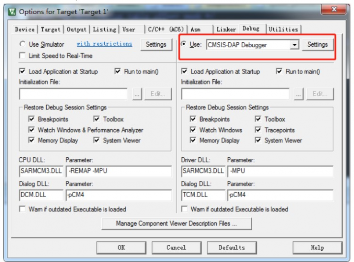
首先移植rtthread?nano,我使用的nano版本不是最新的,是3.1.3,建立工程架構以及添加頭文件路徑
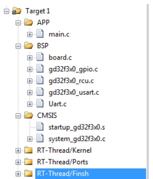
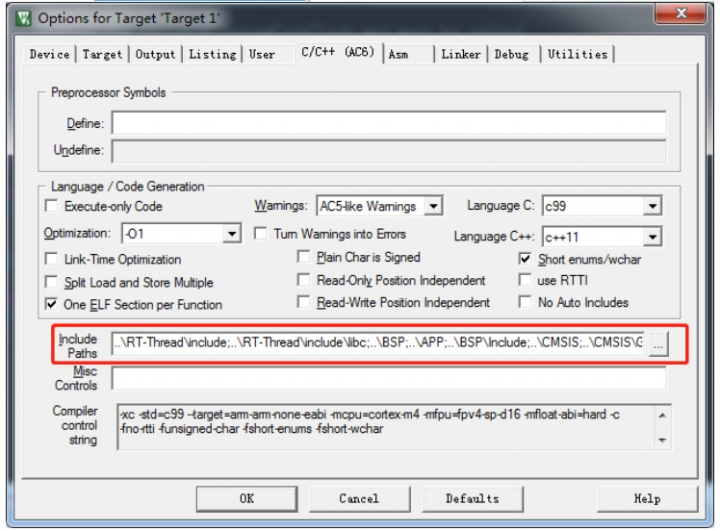
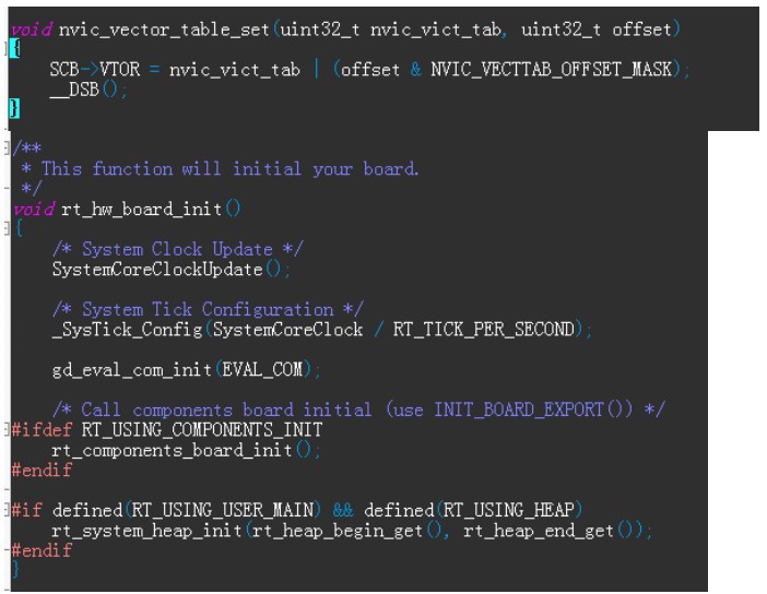
修改一些配置,nvic_vector_table_set的定義和finsh所需要的串口的配置
void gd_eval_com_init(uint32_t com)
{
    uint32_t COM_ID = 0U;

    if(EVAL_COM == com){
        COM_ID = 0U;
    }else{
    }

    /* enable COM GPIO clock */
    rcu_periph_clock_enable(EVAL_COM_GPIO_CLK);

    /* enable USART clock */
    rcu_periph_clock_enable(COM_CLK[COM_ID]);

    /* connect port to USARTx_Tx */
    gpio_af_set(EVAL_COM_GPIO_PORT, EVAL_COM_AF, COM_TX_PIN[COM_ID]);

    /* connect port to USARTx_Rx */
    gpio_af_set(EVAL_COM_GPIO_PORT, EVAL_COM_AF, COM_RX_PIN[COM_ID]);

    /* configure USART Tx as alternate function push-pull */
    gpio_mode_set(EVAL_COM_GPIO_PORT, GPIO_MODE_AF, GPIO_PUPD_PULLUP, COM_TX_PIN[COM_ID]);
    gpio_output_options_set(EVAL_COM_GPIO_PORT, GPIO_OTYPE_PP, GPIO_OSPEED_10MHZ, COM_TX_PIN[COM_ID]);

    /* configure USART Rx as alternate function push-pull */
    gpio_mode_set(EVAL_COM_GPIO_PORT, GPIO_MODE_AF, GPIO_PUPD_PULLUP, COM_RX_PIN[COM_ID]);
    gpio_output_options_set(EVAL_COM_GPIO_PORT, GPIO_OTYPE_PP, GPIO_OSPEED_10MHZ, COM_RX_PIN[COM_ID]);

    /* USART configure */
    usart_deinit(com);
    usart_baudrate_set(com, 115200U);
    usart_receive_config(com, USART_RECEIVE_ENABLE);
    usart_transmit_config(com, USART_TRANSMIT_ENABLE);

    usart_enable(com);
}
 //實現該函數,才能使用rt_kprintf
void rt_hw_console_output(const char *str)
{
    /* 進入臨界段 */
    rt_enter_critical();
    while(*str!='?')
    {
        /* 換行 */
        if (*str == 'n')//RT-Thread 系統中已有的打印均以 n 結尾,而并非 rn,所以在字符輸出時,需要在輸出 n 之前輸出 r,完成回車與換行,否則系統打印出來的信息將只有換行
        {
            usart_data_transmit(USART0, 'r');
            while(usart_flag_get(USART0, USART_FLAG_TC)== RESET);
        }

        usart_data_transmit(USART0, *(str++));
        while(usart_flag_get(USART0, USART_FLAG_TC)== RESET);
    }

    /* 退出臨界段 */
    rt_exit_critical();  //注意:使用進入臨界段語句rt_enter_critical(); 一定要使用退出臨界段語句 rt_exit_critical();否則調度器鎖住,無法進行調度

}
//使用Finsh組件三步驟:1.實現該函數及rt_hw_console_output函數;2.rtconfig.h中開啟RT_USING_FINSH宏;3.添加Finsh組件(cmd.c、msh.c、shell.c),
char rt_hw_console_getchar(void)
{
    //查詢方式實現,記得將Usart1初始化中的中斷接收配置相關代碼注釋掉
    int ch = -1;
    /*等待串口1輸入數據*/
    if(usart_flag_get(USART0, USART_FLAG_RBNE) != RESET)
     {
        ch = (int)usart_data_receive(USART0);
        usart_flag_clear(USART0, USART_FLAG_RBNE);
     }
     else
     {
         if(usart_flag_get(USART0, USART_FLAG_ORERR) != RESET)
         {
             usart_flag_clear(USART0, USART_FLAG_ORERR);
         }
         rt_thread_mdelay(10);
     }
     return ch;
}
main函數創建一個led線程
#include
#include
#include "gd32f3x0_rcu.h"
#include "gd32f3x0_gpio.h"
#include "Uart.h"

static rt_thread_t led_thread;

void led_init(void)
{
    /* enable the LED GPIO clock */
    rcu_periph_clock_enable(RCU_GPIOA);
    /* configure led GPIO port */
    gpio_mode_set(GPIOA, GPIO_MODE_OUTPUT, GPIO_PUPD_NONE, GPIO_PIN_8);
    gpio_output_options_set(GPIOA, GPIO_OTYPE_PP, GPIO_OSPEED_50MHZ, GPIO_PIN_8);
}

void led_thread_entry(void *parameter)
{
    led_init();
    while(1)
    {
        /* turn on led */
        gpio_bit_write(GPIOA, GPIO_PIN_8, SET);
        rt_thread_mdelay(2000);
        /* turn off led */
        gpio_bit_write(GPIOA, GPIO_PIN_8, RESET);
        rt_thread_mdelay(2000);
    }
}

void TaskInit(void)
{
    led_thread = rt_thread_create("ledThread",         /* 線程名字 */
                                    led_thread_entry,  /* 線程入口函數 */
                                    RT_NULL,           /* 線程入口函數參數 */
                                    256,               /* 線程棧大小 */
                                    2,                 /* 線程的優先級 */
                                    10                 /* 線程時間片 */
                                );
    if(led_thread != RT_NULL)
    {
        rt_thread_startup(led_thread);
    }
}

int main()
{
     TaskInit();
}
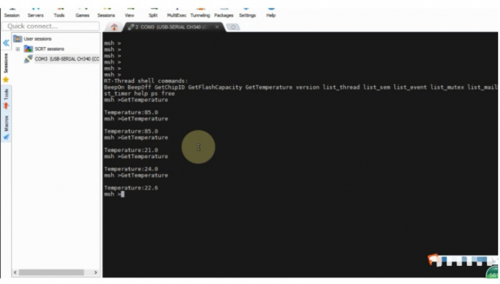
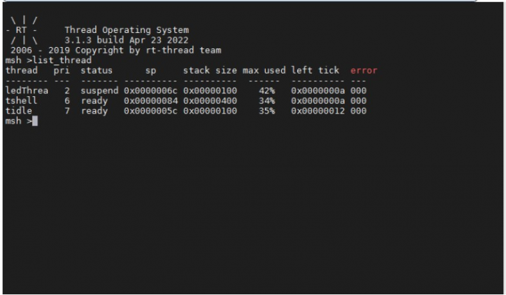
用GDlink下載代碼,用finsh可查看led線程創建成功。
同樣地,再創建一個ds18b20的讀取任務,ds18b20的溫度讀取流程:復位->發 SKIP?ROM?命令(0XCC)->發開始轉換命令(0X44)->延時->復位->發送 SKIP ROM 命令(0XCC)->發讀存儲器命令(0XBE)->連續讀出兩個字節數據(即
溫度)->結束。
貼出部分關鍵代碼
/*
 *主機給從機發送復位脈沖
 */
static void DS18B20_Rst(void)
{
    /* 主機設置為推挽輸出 */
    DS18B20_Mode_Out_PP();

    macDS18B20_DQ_0;
    /* 主機至少產生480us的低電平復位信號 */
    rt_hw_us_delay(750);

    /* 主機在產生復位信號后,需將總線拉高 */
    macDS18B20_DQ_1;

    /*從機接收到主機的復位信號后,會在15~60us后給主機發一個存在脈沖*/
    rt_hw_us_delay(15);
}


/*
 * 檢測從機給主機返回的存在脈沖
 * 0:成功
 * 1:失敗
 */
static uint8_t DS18B20_Presence(void)
{
    uint8_t pulse_time = 0;

    /* 主機設置為上拉輸入 */
    DS18B20_Mode_IPU();

    /* 等待存在脈沖的到來,存在脈沖為一個60~240us的低電平信號
     * 如果存在脈沖沒有來則做超時處理,從機接收到主機的復位信號后,會在15~60us后給主機發一個存在脈沖
     */
    while( macDS18B20_DQ_IN() && pulse_time<100 )
    {
        pulse_time++;
        rt_hw_us_delay(1);
    }
    /* 經過100us后,存在脈沖都還沒有到來*/
    if( pulse_time >=100 )
        return 1;
    else
        pulse_time = 0;

    /* 存在脈沖到來,且存在的時間不能超過240us */
    while( !macDS18B20_DQ_IN() && pulse_time<240 )
    {
        pulse_time++;
        rt_hw_us_delay(1);
    }
    if( pulse_time >=240 )
        return 1;
    else
        return 0;
}


/*
 * 從DS18B20讀取一個bit
 */
static uint8_t DS18B20_ReadBit(void)
{
    uint8_t dat;

    /* 讀0和讀1的時間至少要大于60us */
    DS18B20_Mode_Out_PP();
    /* 讀時間的起始:必須由主機產生 >1us <15us 的低電平信號 */
    macDS18B20_DQ_0;
    rt_hw_us_delay(10);

    /* 設置成輸入,釋放總線,由外部上拉電阻將總線拉高 */
    DS18B20_Mode_IPU();
    //rt_hw_us_delay(2);

    if( macDS18B20_DQ_IN() == SET )
        dat = 1;
    else
        dat = 0;

    /* 這個延時參數請參考時序圖 */
    rt_hw_us_delay(45);

    return dat;
}


/*
 * 從DS18B20讀一個字節,低位先行
 */
static uint8_t DS18B20_ReadByte(void)
{
    uint8_t i, j, dat = 0;

    for(i=0; i<8; i++)
    {
        j = DS18B20_ReadBit();
        dat = (dat) | (j<>1;
        /* 寫0和寫1的時間至少要大于60us */
        if (testb)
        {
            macDS18B20_DQ_0;
            /* 1us < 這個延時 < 15us */
            rt_hw_us_delay(8);

            macDS18B20_DQ_1;
            rt_hw_us_delay(58);
        }
        else
        {
            macDS18B20_DQ_0;
            /* 60us < Tx 0 < 120us */
            rt_hw_us_delay(70);

            macDS18B20_DQ_1;
            /* 1us < Trec(恢復時間) < 無窮大*/
            rt_hw_us_delay(2);
        }
    }
}


 /**
  * @brief  跳過匹配 DS18B20 ROM
  * @param  無
  * @retval 無
  */
static void DS18B20_SkipRom ( void )
{
    DS18B20_Rst();

    DS18B20_Presence();

    DS18B20_WriteByte(0XCC);        /* 跳過 ROM */

}


 /**
  * @brief  執行匹配 DS18B20 ROM
  * @param  無
  * @retval 無
  */
static void DS18B20_MatchRom ( void )
{
    DS18B20_Rst();

    DS18B20_Presence();

    DS18B20_WriteByte(0X55);        /* 匹配 ROM */

}


/*
 * 存儲的溫度是16 位的帶符號擴展的二進制補碼形式
 * 當工作在12位分辨率時,其中5個符號位,7個整數位,4個小數位
 *
 *         |---------整數----------|-----小數 分辨率 1/(2^4)=0.0625----|
 * 低字節  | 2^3 | 2^2 | 2^1 | 2^0 | 2^(-1) | 2^(-2) | 2^(-3) | 2^(-4) |
 *
 *
 *         |-----符號位:0->正  1->負-------|-----------整數-----------|
 * 高字節  |  s  |  s  |  s  |  s  |    s   |   2^6  |   2^5  |   2^4  |
 *
 *
 * 溫度 = 符號位 + 整數 + 小數*0.0625
 */
 /**
  * @brief  在跳過匹配 ROM 情況下獲取 DS18B20 溫度值
  * @param  無
  * @retval 溫度值
  */
float DS18B20_GetTemp_SkipRom ( void )
{
    uint8_t tpmsb, tplsb;
    short s_tem;
    float f_tem;

    DS18B20_SkipRom ();
    DS18B20_WriteByte(0X44);                /* 開始轉換 */

    DS18B20_SkipRom ();
    DS18B20_WriteByte(0XBE);                /* 讀溫度值 */

    tplsb = DS18B20_ReadByte();
    tpmsb = DS18B20_ReadByte();

    s_tem = tpmsb<<8;
    s_tem = s_tem | tplsb;

    if( s_tem < 0 )        /* 負溫度 */
        f_tem = (~s_tem+1) * 0.0625;
    else
        f_tem = s_tem * 0.0625;

    return f_tem;
}
